In Part 1 of this series, I introduced you to the RISC-V computer instruction set architecture and described some first steps using an example device. In this article, I continue working with PlatformIO to program the GD32VF103CBT6 chip on the Sipeed Longan Nano development board. Specifically, we’ll use one of the onboard serial ports of the chip for both device programming and communication with the host PC.
Setup for Serial Communication
The GD32V series of chips from GigaDevice offer multiple bootloader options, including:
- USB Device Firmware Update (DFU)
- Serial bootloader using USART0 or USART1
The USB DFU method was demonstrated in the previous article. A “rolling†button press sequence on the Longan Nano board (“roll UP to UPloadâ€) puts the device in bootloader mode. This time, we’ll use a serial port to both program the device and communicate with the host PC.
Two changes have to be made to switch over from USB to serial communication. First, we have to connect the serial port (USART0) on the GD32VF103 chip to the host PC via a USB-TTL adapter. You can use any adapter you like, as long as it provides an option to select the output voltage as being 3.3V, to be compatible with the GD32V chip. Here is a photo of the one I used:
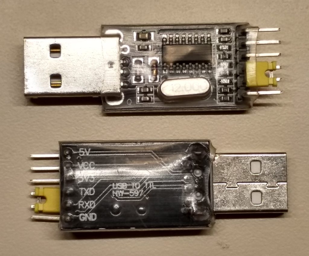
Figure 1. The USB-TTL adapter will connect to the Sipeed Longan Nano. This model uses the CH430G interface chip.
Here are the necessary connections (color selection is entirely up to you):
USB-TTL —- Sipeed Longan Nano
- 3.3V, 3.3V, orange
- GND, GND, black
- TXD, R0, red
- RXD, T0, green
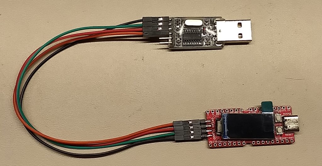
Figure 2. Connect USB-TTL adapter to Sipeed Longan Nano. Note that transmit and receive are swapped on both ends.
Next, we change the upload_protocol specified in the project’s platformio.ini file from
upload_protocol = dfu
… to …
upload_protocol = serial
We need not indicate which port to use, baud rate or any other details like that. PlatformIO just figures it all out, which was nice.
I applied these changes first to the existing (and working!) example from the previous article that blinked all three colors of the on-board LED. It’s important to perform the “button roll†first, to prepare the chip for bootloading, before hitting the “Upload†icon. For short demonstration programs such as this, the time to program the device is still quite tolerable, even using the serial port.
A Bad Assumption
Here’s where a Bad Assumption came into play. Since the bootloader had to configure the on-board USART (universal synchronous/asynchronous receiver/transmitter) to communicate to the PC, I assumed that the USART would remain properly initialized, and that we could just start using it.
That turns out not to be the case. Which is OK, really. One shouldn’t depend on someone else’s software to set up one’s environment for one, should one? The bootloader looks to be doing a good job of covering its tracks as it hands off to the application program.
Create a New Project
Let’s create a new project for these further experiments with the Sipeed Longan Nano. In PlatformIO, go to the PlatformIO Home page. This page opens itself by default after you open the application, unless you tell it not to. If the Home page is not already being displayed, click on the PlatformIO icon (alien bug head?) on the left edge of the screen, then select “PIO Home/Open†from the Quick Access menu at the bottom left of the screen. There is also a Home icon on the bottom edge of the screen that looks like a little house. It can take a moment to load this page, because it has to contact the PlatformIO home planet.
On the left edge of the PlatformIO Home tab, you can select the Home icon, then find the “New Project†button in the Quick Access group at the top right. Alternatively, you can select the Projects icon and see a list of your current projects. The “Create New Project†button is at the top right of the screen.
Project Wizard
Either method brings up the Project Wizard dialog. Here you enter a project name and select which board to use. The list of supported boards is large and growing, so just start typing “longan nano†and it will start filtering out the non-matching options. This will pre-populate the “Framework†drop-down with “GigaDevice GD32V SDK†(what we want), as well as allow you to select “Arduinoâ€, which we will explore in a future article. Click the “Finish†button and your new project is set up for you.
Now you have an “empty†project for the GD32V framework, but it’s not really empty. There’s already a folder structure present that is well-organized for PlatformIO’s purposes. You can explore this structure using PlatformIO’s Explorer. Open the Explorer by clicking on the Explorer icon (stacked papers?) at the top left edge of the window.
Create a New Source File
In the Workspace section, expand the folder structure for your newly created project and find the “src†(source code) folder. Right-clicking on the “src†folder brings up a context menu. Select “New File†from this menu. You will see a blank line into which you should type the name of your source code. A good choice here would be “main.câ€, as it will contain our C program’s main() function, but feel free to express yourself. This will open a new editor with a tab at the top of the window.
Enter the following code into the editor
/* main.c
    part of GD32V-USART0 project
    Dale Wheat
    28 Feb 2020
*/

#include "gd32vf103.h"
#include <stdio.h>

int _put_char(int c) {
    usart_data_transmit(USART0, (uint8_t) c);
    while(usart_flag_get(USART0, USART_FLAG_TBE) == RESET);
    return c;
}

void main(void) {

    int i = 0; // iterator

    // initialize USART0

    rcu_periph_clock_enable(RCU_GPIOA);
    rcu_periph_clock_enable(RCU_USART0);
    gpio_init(GPIOA, GPIO_MODE_AF_PP, GPIO_OSPEED_50MHZ, GPIO_PIN_9);
    gpio_init(GPIOA, GPIO_MODE_IN_FLOATING, GPIO_OSPEED_50MHZ, GPIO_PIN_10);

    usart_deinit(USART0);
    usart_baudrate_set(USART0, 9600);
    usart_parity_config(USART0, USART_PM_NONE);
    usart_word_length_set(USART0, USART_WL_8BIT);
    usart_stop_bit_set(USART0, USART_STB_1BIT);
    usart_hardware_flow_rts_config(USART0, USART_RTS_DISABLE);
    usart_hardware_flow_cts_config(USART0, USART_CTS_DISABLE);
    usart_receive_config(USART0, USART_RECEIVE_ENABLE);
    usart_transmit_config(USART0, USART_TRANSMIT_ENABLE);
    usart_enable(USART0);

    while(1) {
        //usart_data_transmit(USART0, '!');
        printf("Hello, GD32V world!  i = %i\n", i);
        i++;
        for(volatile uint32_t n = 0; n < 10000000; n++); // delay
    }
}

// [end-of-file]
Listing 1. Test program for serial port testing
Once you’ve got this code into the editor, be sure to save it using either menu item “File/Save†or Ctrl+S.
Modify Project Configuration File
The Project Wizard created a basic project configuration file for you, named platformio.ini. Select this file using the Explorer and add the following two lines:
build_flags = -ffreestanding
upload_protocol = serial
Listing 2. Add these two lines to your project configuration file.
The first line, build_flags, allows you to send command-line options to the GCC compiler. You may have noticed that the main() function in this example is declared as returning “voidâ€, as is proper and fitting for an embedded application. The C programming language, originally developed for application programs, expects support from an operating system. The default and expected return value type is an “intâ€. To avoid the compiler complaining about this heretical behavior, we pass this option (-ffreestanding) to the compiler and all is well.
The second line, upload_protocol, is more important. Here we assign it a value of “serialâ€. PlatformIO does the rest.
Remember to save your newly-edited configuration file and then we’ll be ready to do a test build and make sure all the pieces are in place.
Time to Build
On the bottom edge of the screen is a toolbar we will find quite handy. To the right of the Home icon is the Build icon (check mark). Click this and PlatformIO will try to build your project. Ideally, you will see the following (or similar) text in the lower part of the window:
CONFIGURATION: https://docs.platformio.org/page/boards/gd32v/sipeed-longan-nano.html
PLATFORM: GigaDevice GD32V 1.1.2 > Sipeed Longan Nano
HARDWARE: GD32VF103CBT6 108MHz, 32KB RAM, 128KB Flash
DEBUG: Current (altera-usb-blaster) External (altera-usb-blaster, gd-link, jlink, rv-link, sipeed-rv-debugger, um232h)
PACKAGES:
 - framework-gd32vf103-sdk 1.0.0
 - toolchain-gd32v 9.2.0
LDF: Library Dependency Finder -> http://bit.ly/configure-pio-ldf
LDF Modes: Finder ~ chain, Compatibility ~ soft
Found 0 compatible libraries
Scanning dependencies...
No dependencies
Building in release mode
`buildhex' is up to date.
Checking size .pio\build\sipeed-longan-nano\firmware.elf
Advanced Memory Usage is available via "PlatformIO Home > Project Inspect"
RAM:   [=         ]   7.0% (used 2310 bytes from 32768 bytes)
Flash: [=         ]   6.5% (used 8456 bytes from 131072 bytes)
========================= [SUCCESS] Took 0.83 seconds ===============================================
Terminal will be reused by tasks, press any key to close it.
Upload the Newly Built Code
If all went well, we are ready to upload this test code to the device. Perform the bootloader “button roll†to prepare the device, then select the Upload icon (left arrow) in the toolbar. You should see this (very long) bunch of stuff appear in the Terminal window at the bottom of the screen:
Configuring upload protocol...
AVAILABLE: altera-usb-blaster, gd-link, jlink, rv-link, serial, sipeed-rv-debugger, um232h
CURRENT: upload_protocol = serial
Looking for upload port...
Auto-detected: COM15
Uploading .pio\build\sipeed-longan-nano\firmware.bin
stm32flash 0.4

http://stm32flash.googlecode.com/
Using Parser : Raw BINARY
Interface serial_w32: 115200 8E1
Version      : 0x30
Option 1     : 0x00
Option 2     : 0x00
Device ID    : 0x0410 (Medium-density)
- RAM        : 20KiB  (512b reserved by bootloader)
- Flash      : 128KiB (sector size: 4x1024)
- Option RAM : 16b
- System RAM : 2KiB
Write to memory
Erasing memory
Wrote address 0x08000100 (3.02%)
Wrote address 0x08000200 (6.05%)
Wrote address 0x08000300 (9.07%)
Wrote address 0x08000400 (12.09%)
Wrote address 0x08000500 (15.12%)
Wrote address 0x08000600 (18.14%)
Wrote address 0x08000700 (21.16%)
Wrote address 0x08000800 (24.19%)
Wrote address 0x08000900 (27.21%)
Wrote address 0x08000a00 (30.23%)
Wrote address 0x08000b00 (33.25%)
Wrote address 0x08000c00 (36.28%)
Wrote address 0x08000d00 (39.30%)
Wrote address 0x08000e00 (42.32%)
Wrote address 0x08000f00 (45.35%)
Wrote address 0x08001000 (48.37%)
Wrote address 0x08001100 (51.39%)
Wrote address 0x08001200 (54.42%)
Wrote address 0x08001300 (57.44%)
Wrote address 0x08001400 (60.46%)
Wrote address 0x08001500 (63.49%)
Wrote address 0x08001600 (66.51%)
Wrote address 0x08001700 (69.53%)
Wrote address 0x08001800 (72.56%)
Wrote address 0x08001900 (75.58%)
Wrote address 0x08001a00 (78.60%)
Wrote address 0x08001b00 (81.62%)
Wrote address 0x08001c00 (84.65%)
Wrote address 0x08001d00 (87.67%)
Wrote address 0x08001e00 (90.69%)
Wrote address 0x08001f00 (93.72%)
Wrote address 0x08002000 (96.74%)
Wrote address 0x08002100 (99.76%)
Wrote address 0x08002114 (100.00%) Done.
GET returns unknown commands (0x 6)
Starting execution at address 0x08000000... done.
================================= [SUCCESS] Took 2.22 seconds ===================================
Terminal will be reused by tasks, press any key to close it.
It’s interesting to me that PlatformIO uses the “stm32flash†program to upload the code. Here we see yet another similarity to the familiar STM32 family of parts from STmicroelectronics that we all know and love (or not). Unfortunately, the link given no longer computes. Also note that the reported RAM (20KiB) is incorrect, (-C8T6 instead of -CBT6?) but does not seem to affect the programming of the flash memory.
Testing the New Code
To see if the code is actually working or not, select the Serial Monitor toolbar icon (electrical plug? South-facing AND gate?). This will launch the serial communications program miniterm within the window at the bottom part of the screen. You should see “Hello, GD32V world!†followed by an ever-incrementing counter, about once a second:
Hello, GD32V world!  i = 300
Hello, GD32V world!  i = 301
Hello, GD32V world!  i = 302
Hello, GD32V world!  i = 303
Hello, GD32V world!  i = 304
Hello, GD32V world!  i = 305
Hello, GD32V world!  i = 306
Hello, GD32V world!  i = 307
Hello, GD32V world!  i = 308
Hello, GD32V world!  i = 309
Hello, GD32V world!  i = 310
Hello, GD32V world!  i = 311
Hello, GD32V world!  i = 312
Hello, GD32V world!  i = 313
Hello, GD32V world!  i = 314
Code Review
Let’s review the code a bit and see what we have.
After a short section of program comments identifying the file, project, author and date, we have a couple of #include statements:
#include "gd32vf103.h"
#include <stdio.h>
The first one defines all the interesting bits of the GD32VF103 chip, as far as pointers to peripherals and other useful information, as well as further linking to other files that bring in all the details about the standard peripheral library, which comes in handy presently.
The second statement gives us access to C’s standard IO (input and output) library, which includes the ever-popular printf() function.
Interfacing with printf()
To actually use the printf() function, we have to define a function called _put_char(). This is because the printf() function itself has no idea of where to send all those formatted characters. In this instance, we want to send them straight out the serial port known as USART0. This is the easiest port to use for this experiment, as these pins are brought out to the header on the edge of the Sipeed Longan Nano board.
The main() Function
From a programmer’s perspective, the fun starts with the main() function. In reality, some system initialization occurs before the main() function starts its work. This includes setting up the stack pointers, initializing the memory areas and cranking up the clock speed.
In our main() function, we declare an integer, i, that will be used as our loop counter later.
Next are the several steps necessary to properly initialize the serial port. This is accomplished using calls to the standard peripheral library, which takes a lot of tedium out of getting things working quickly.
Wake Up, Peripherals!
One thing that might be surprising to embedded programmers coming from, e.g., Arduino or Microchip PIC backgrounds is that almost all of the peripheral devices in the GD32V family, much like the embedded ARM devices, are powered off when the chip begins operation. Each peripheral must be explicitly enabled before use. This saves a lot of power, as unused sections of the chip remain dormant and take little or no power.
Additionally, since most pins of the GD32V device can be either inputs, outputs or serve as connections to the internal peripherals, you have to explicitly define which pins are used for what purposes. Only then do we get to the part where we can set up the individual peripherals to perform as we wish.
USART Configuration
There is a very particular sequence of events that must take place to properly get the USART up and running. All these steps are greatly simplified by using the standard peripheral library calls you see in the example program given. The parameters (9600 baud, 8 data bits, no parity, plus others) match the default communication settings of the miniterm program invoked by PlatformIO in its Serial Monitor function.
The Endless Loop
Most embedded applications follow a very simple pattern: perform some initialization, then go into a perpetual loop. This has been immortalized in Arduino’s setup() and loop() functions. We have our own infinite loop in our example, consisting of a while(1) control block. Since the constant “1†always evaluates to “true†by the C compiler, this loop will continue until something drastic happens. This could be an external reset, interrupt or ultimately power loss.
Within the loop, look for a statement that has been commented out, namely:
//usart_data_transmit(USART0, '!');
This was a call to the standard peripheral library that sent a single character to the USART for transmission. I used this for the first test of the program, before adding the printf() support. Upon opening the Serial Monitor, I was rewarded with a trail of exclamation points marching across the screen. Success!
Then Things Got Weird
Like Edison, I couldn’t be happy with my first glowing light bulb: I had to mess with it until it broke. Not surprisingly, this didn’t take long.
The first thing I tried was to increase the delay time between exclamation points. Simply adding a zero to the constant comparison value in the for() loop had no obvious effect on the pace of the points. Another zero also had no effect. More annoyed than puzzled, I proceeded with setting up support for formatted output using the printf() function from C’s standard input and output library.
Really Weird
Adding the printf() function support was simply a matter of adding the _put_char() function into the program. Nice! I was happy for many milliseconds as I watched my formatted “Hello, world!†statements scroll down the page. Oddly, however, the “i = 0†counter stayed at, oddly, zero. Did I forget to increment the variable? I’ve done that before. But no, that was not the case.
Some amount of time and head-scratching elapsed. This did not make sense. Surely I hadn’t run into some subtle compiler bug already. Then it hit me.
When Does i = 0?
The only time that the variable i should equal zero is right after the program starts… which happens to be right after the power comes on (or the reset button is pushed, which wasn’t happening). Glancing at the power LED on the Sipeed Longan Nano bard, I saw that it was flickering. Not good. And yet, it was good, as this would explain both the non-incrementing counter as well as the lack of timing changes induced by orders of magnitude different parameters previously seen.
Ultimately, the issue was that I had plugged the USB-TTL adapter into a USB hub, and not directly into my PC. It seems that the voltage drop through the hub, then through the voltage regulator on the USB-TTL adapter and then through the jumper wires to the development board resulted in a low-voltage condition for the system. Plugging the USB-TTL adapter directly into my PC solved the problem.
Conclusion
We now have two proven and (relatively) convenient methods to program the device: USB DFU and serial. Additionally, we have a bi-directional communication channel to the host PC that we can use for whatever we want, including simple debugging.
Another important advantage, which we had in the previous article but didn’t really explore, was access to the complete standard peripheral library for this device. This will obviate many hours of tedious research into datasheets, which will please some and annoy others.
Next Time
Continuing in this series of articles, I hope to explore a more in-depth method of debugging these chips. Stay tuned!
Things I Learned
PlatformIO is a rich environment that can be overwhelming at times, especially for new users. Additionally, there are almost always more than one way to accomplish any specific tasks, which is both useful and confusing.
Google Docs has a short but non-trivial learning curve for me. There are very few options when it comes to text styles. One of the default paragraph styles (“Normal textâ€) needed some extra space after each paragraph. This was easy to set using menu item “Format/Line spacing/Add space after paragraphâ€. Then selecting menu item “Format/Paragraph styles/Options/Save as my default styles†should make this change persistent.