How It Began
About a year ago, my friend Brady Pamplin W5LH was teaching a class at the Dallas Makerspace. Brady teaches a variety of Arduino and microcontroller-related classes. See his web site for a list of what’s available. This class was about how to use NeoPixel LED strips with Arduino. NeoPixels are addressable RGB (red, green and blue) LED chips. Most importantly, it is not hard to chain them together. He liked an article he read by Josh Levine about how to make a “Times Square” style scrolling sign. Josh’s article suggested you could make one as large as you wanted for around $15 a foot. Brady built one of these signs, and I helped him make a few small improvements.
A First Prototype

Brady then quickly built his own prototype to show off the idea to his students. The main problem was that he would give away the individual LED strips to students after the class. Consequently, the sign was often out of operation until he could make more strips. He posted a short video of the sign in operation on his web site, along with its Arduino sketch.
Dale Gets Involved
Brady’s sign worked splendidly and was a very attention-getting item, indeed. The only thing he wanted to add was the ability to display static (i.e., non-scrolling) text. I volunteered to look at the Arduino sketch and possibly add some functions to display the static text.
Once I looked at the original sketch from Josh’s web site, I was immediately impressed with two aspects of the design. First, the software does not use a memory-hungry frame buffer. Instead, it decodes the bit patterns of the individual letters and symbols on the fly. This allows very long messages to be stored in the flash memory of the Arduino and not be limited to the relatively small amount of static RAM. Second, the design pumps out seven bitstreams in parallel using highly-optimzed assembler code. Each bitstream goes to the individual LED strips via separate GPIO output pins. Thus the performance-constrained Arduino can crank out fairly high frame rates. More advanced microcontrollers use DMA (direct memory access) peripherals to do the same trick.
Tweaking the Code
I added a new function, showText(), that specified the text to display and the color to use. It simply calls an existing function, sendString(), once instead of repeatedly in a loop which was how Josh achieved the scrolling action. The cli() function* disables hardware interrupts for the timing-critical section of code used to update the NeoPixels. The sei() function* re-enables the hardware interrupts afterwards.
* actually they are macros for the AVR assembly instructions CLI (clear global interrupt enable bit) and SEI (set global interrupt enable bit).
void showText(const char* p, uint8_t red, uint8_t green, uint8_t blue) {
   cli();
   sendString(p, 0, red, green, blue);
   sei();
}
This function would let you display a non-scrolling message for one second (1,000 milliseconds) by calling it like this:
showText("Sample", 0x40, 0x00, 0x00); delay(1000); // red
The problem with this approach is that it used up precious static RAM; one byte for each character in the passed string. Then I cooked up another version of the same function. I did so using C++’s function overloading feature. This used either strings that were declared as const (constant) or specified using the FlashStringHelper modifier.
 void showText(const __FlashStringHelper* p, uint8_t red, uint8_t green, uint8_t blue) {
   cli();
   PGM_P p1 = reinterpret_cast(p);
   while (1) {
     unsigned char c = pgm_read_byte(p1++);
     if (c == 0) break;
     sendChar(c, 0, red, green, blue);
   }
   sei();
 }
You can have multiple versions of the same function, in this case showText(), as long as they take different parameters. As you can see, I had to add some trickery in the code to get it to take a string straight out of the flash memory. Here are some examples of how it can be used:
static char test[] = "-TEST-";
showText(test, 0x40, 0x00, 0x00); delay(1000); // red only
showText(F("RED---"), 0x40, 0x00, 0x00); delay(1000); // red
A More Robust Hardware Design
Brady built the sign with a cardboard (ahem, corrugated paperboard) substrate and various kinds of tape. It used an Arduino Nano (Brady’s choice for his Arduino classes) and a solderless breadboard. There were various wires going hither & thither. While this certainly worked and was spectacularly eye-catching, it was not road-worthy. It really needed to be, because by now Brady was taking the sign to other events.
I suggested to Brady a partial solution to the issue: a custom printed circuit board (PCB) to hold everything together. This would eliminate a large number of vulnerable electrical connections (in the form of breadboard jumpers) and make it a little easier to transport the sign to various events. The idea sort of sat there for a month or two. Brady would occasionally ask how it was coming, and I would typically say it would be ready “in three weeks”. Finally, on 2 October 2019, I added this project to my “official” list of Things to Do.
Gathering Customer Requirements
Brady and I got together on 8 October 2019 to discuss and finalize a definitive list of requirements for the project. Over some tacos, we set out the major check-list items for the project:
- Arduino Nano based system, socketed
- +5V 4A 2.1mm power supply
- Right-angle 3 pin female headers for LED strips
- Square pixel aspect ratio
- 2 non-dedicated potentiometers with knobs for adjustments
- 4 mounting holes
- Leave USB cable path clear
- LED connectors on right-hand side of PCB
- Check data bit order (lowest row is D0/TX)
Proof of Concept
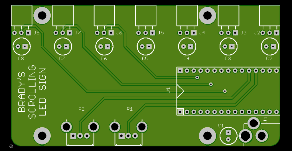
A preliminary schematic and PCB layout in EAGLE 7.7.0 had already been made. Making sure the design met all the customer requirements, I uploaded the design to OSH Park and got this nice board rendering. This I showed to Brady and he said it looked like it would work.
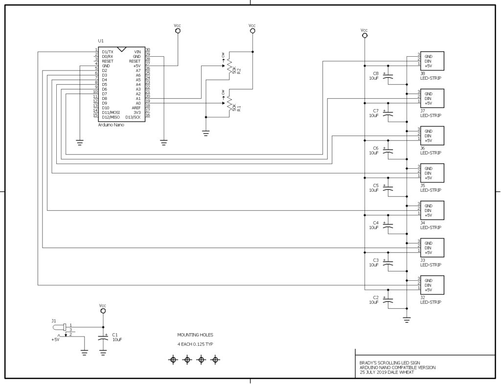
Schematic Diagram
Here is the schematic diagram of the circuit. Click the image to download or view the diagram as a PDF.
Customer Green Light
Since everything looked good so far, on 16 October 2019 I ordered three prototype PCBs from my favorite short-run PCB fabricator, OSH Park. On 31 October 2019, the prototype boards arrived. I built one and gave it to Brady for testing. I didn’t have enough LED strips on hand to test it completely here in the lab.
On 21 November 2019, I received the remaining parts I needed to finish the second prototype PCB that I had promised Brady. The board was delivered on 26 November 2019.
A Sign of My Very Own
With my one remaining prototype PCB in hand, I decided to build my own Scrolling LED Sign. I ordered a reel of NeoPixel-compatible WS2812B LEDs (5 meters, 60 LEDs per meter, 300 LEDs total) from Amazon [product link]. This was on 28 January 2020. The very next day, my order arrived. Gotta love Amazon Prime for this kind of stuff*. It even came with a “tester” device that drives the whole strip in a variety of patterns.
Since the nice, round number 300 does not divide evenly by 7, I cut up the five meter strip into six strips of 43 LEDs with one strip left over with only 42 LEDs. To plug into the sockets on the driver board, I soldered three-pin headers to the input ends of the seven strips.
*I very rarely use Amazon Prime, mostly due to concerns about sustainability, but in some situations the ultra-mega-convenience wins over my love of the Earth and its future inhabitants.
Even More Testing
Laying out the loose strips on my work table, I was able to upload a slightly modified sketch and test the sign as a whole. I adjusted the number of PIXELS to 43, which was larger than Brady’s original sign.
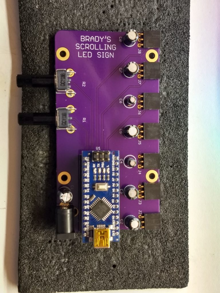
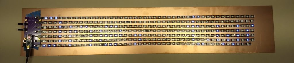
Mounting to an Artisan Substrate
Attaching the adhesive-backed LED strips to a large panel of copper-clad PCB material I had in the lab, I was able to connect everything together. I could have scrubbed the copper to get rid of the fingerprints, etc., but I decided to leave it as it was and in fact invite oxidation, which should result in a dramatic and lovely patina in time. Since a solid sheet of copper is that very last thing you want to rest your circuits on, I put some famous blue tape under the driver board to insulate it a bit.
In Summary
Transitioning your friends to “customers” doesn’t always go well, in my experience. This experience turned out to be one of the delightful exceptions. Brady seems to be quite happy with his new signs, and I know I am. He is planning on installing one of his signs at Tanner Electronics to advertise his classes across the street at the Dallas Makerspace.
Additionally, I have created a new Scrolling LED Sign kit and added it to my web store. It’s also available at Tanner’s and BG Micro. Right now, you still need to bring your own Arduino Nano, LED strips and regulated +5VDC power supply to complete the build. I am working on sourcing all the bits to be able to offer a “complete” kit for this kind of sign. I’ll let you know when that’s available.