The more observant amongst you may have noted a striking, yellow banner emblazoned across the top of each and every one of the pages of this, your favorite web destination. What could be behind such a serious and dire notification? Rest assured, nothing was amiss. I simply wanted to let you know that I would not be able to ship your orders until Monday, because I had slipped the leash, jumped on a plane and jetted to Seattle to help celebrate my granddaughter Olivia’s third birthday. Now I am returned, everything is as it was, orders are shipping as scheduled and I hope you agree with me that it was totally worth it.
Grandpa Dale helps Olivia celebrate her third birthday. Photo by Elizabeth Wheat.
I’m designing and building a whiteboard plotter as an Arduino demonstration project. I’ll be creating a build log for this project and hope to have a working prototype within a week or so. Stay tuned!
Today I’m happy to announce a new addition to my blinky LED kit line-up, the aptly-named “12 LED circle“, or 12LEDcircle for short. It’s a small, round PCB with 12 bright blue LEDs around the edge. It comes with a pre-programmed microcontroller that lights up the LEDs in various mesmerizing patterns. You can see a demo of the various blinky modes on my YouTube channel.
I wrote another book. This time it’s about building your own electronics lab, titled Building Your Own Electronics Lab. It gives the reader a gentle introduction to electricity and electronics and how to safely learn and play with them. Basic tools and components are discussed and some simple starter projects are presented. The main idea that I tried to put forward is that the electronics hobby is fun. It’s also fun to share with others.
The softcover edition is available in my store! You can also find paperback and e-book versions on Amazon.com, or find it at your favorite bookseller using the ISBN 978-1430243861.
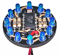
I’ve updated the popular Lux Spectralis kit! The new Lux Spectrlais 2 kit uses three separate LEDs for the red, green and blue color channels. The circuit still does exactly the same thing (blinks multi-colored LEDs). This will make it much easier to modify for custom color combinations. Check out the Lux Spectralis 2 Kit in the store!
The new PCB is a little bit smaller than the previous version. It uses electroless nickel immersion gold (ENIG) plating on all the electrical contacts, which has its own advantages, electrically, but I did it because it’s more beautiful and contrasts well with the black solder mask.
Other improvements:
I simplified the whole thing and reduced the component count. This will make it easier to assemble. You can download your own copy of the assembly instructions.
The kits still comes with a 3xAAA battery holder with a built-in power switch. The lighting modes are identical to the previous version. The price remains the same.
Over the summer, I wrote a book about Arduino internals, called Arduino Internals. It is being published November 16, 2011 by Apress. It has a lot of detailed information about Arduinos as well as Atmel AVRs. There are several projects in the book that illustrate some of the topics. It’s a paperback book that runs to just over 350 pages. There’s also an “ebook” available in several popular formats.
You can buy your very own copy from our store! It’s also available from Amazon. You can also go to your favorite book seller and buy a copy. Just use the ISBN number 978-1430238829. To buy the ebook, go to the book’s page on the Apress web site, apress.com.
This was a very exciting project for me. It’s my first book. I hope you enjoy it.
I’m going to Maker Faire this weekend, May 21st & 22nd! Most of the time, I’ll be in or around the Maker Shed, explaining how vitally important it is to have more blinky LEDs in your life. I’ll also be making a couple of short presentations. Saturday at 11am I’ll be talking about the Breadboard Arduino project. Sunday at 4:30pm I’ll demonstrate the Tiny Wanderer robot. If you can, please come out and say hi!
You can build the Wee Blinky kit using incandescent bulbs instead of the supplied LEDs. Just omit D1, D2 (the LEDs) and R1 and R4 (the current-limiting resistors for the LEDs). Connect one lead of an incandescent bulb to the bottom lead of where the LED was supposed to go, then the other lead to the bottom lead of where the resistor was supposed to go. Repeat for the other side.
Here is a YouTube video using 12V incandescent bulbs:
This is a minimalist USB-to-TTL adapter for use on a solderless breadboard. I designed this to use with my Breadboard Arduino class. It’s based on the FTDI USB UART chip, which is the same, identical chip used on “real” Arduinos, so it uses the same, identical drivers and works on most PCs. The only differences are that it is tiny, it plugs into a breadboard and lines up with the RESET, TXD and RXD pins of an ATmega328 chip (the Arduino main-brain) and it says “Dale Wheat’s USB to TTL” when you plug it in the first time. I make these here in the lab, by hand.
Originally I was only selling these USB-TTL adapters with the Breadboard Arduino kit, but due to popular demand, I am now selling it separately in my online store. You’re more than welcome, however, to make your own using the files provided above. The entire design is placed by me in the Public Domain. Go nuts.
There have been some USB-TTL failures in the field from the very first batch of 100. These are being investigated to try to improve their reliability. Every disappointing and frustrating failure is an opportunity for improvement. If you are having problems with your USB-TTL adapter, please feel free to contact me to see what might be the matter with it. I expect machines and tools to perform their function without a lot of fuss. I’d also like people to use these little gizmos to build interesting and fascinating things and not have to spend lots of time trouble-shooting the components.