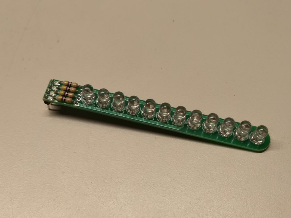
The 12LEDstick is a multiplexed (specifically Charlie-plexed) linear array of twelve bright blue LEDs. It uses four (4) pins to control all twelve LEDs, making it easy to add a lot of LEDs without dedicating a lot of valuable I/O lines. An Arduino library with example sketches is provided to make it easy to add to your next blinky project.
Why do it?
Adding multiple LEDs to a project makes it more visually interesting, useful and engaging. Using a clever multiplexing technique called Charlie-plexing allows up to 12 LEDs to be controlled with only four (4) signals. The LEDs can be mounted directly to the provided PCB for a compact linear array or wired individually to reach wherever you need extra blinky-ness!
Value/Benefit
Wiring up a lot of LEDs can require a correspondingly large number of connections and extra components. The 12LEDstick reduces this to four connections and four current-limiting resistors (provided). The Arduino library and examples sketches will get your project blinking fast and easy.
Who benefits?
Electronic hobbyists can easily add large numbers of LEDs to their projects without needing extra chips, shift-registers, resistors and wiring. Arduino builders can easily add more blinky bling without using up all the precious I/O lines. Any microcontroller that can sink or source 10mA per I/O pin can drive the 12LEDstick.
The 12LEDstick is a multiplexed linear array of blue 5mm LEDs that can be controlled with only four signals. An Arduino library and samples sketches are provided.
Yes, Astute Reader, you have caught me in, shall we say, an “inconsistencyâ€. This product is not “new”, but it is “new to the store”. I have been designing and selling infrared (IR) spotlight kits for decades now. In the past, I was mostly producing these for wholesale customers like BG Micro. Since I have several different models in stock now, I thought I would start making them available in the web store here:
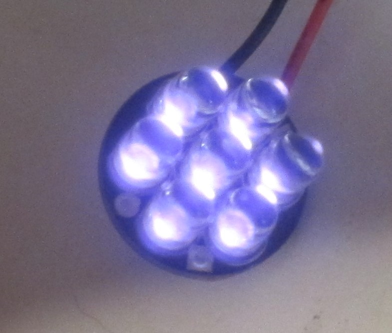
The Mini7Plus IR Spotlight is a compact, low-power infrared (IR) LED array that runs on 12VDC. The round printed circuit board (PCB) is a tiny 0.75 inches (19.05 mm) in diameter; it’s the same size as a US penny. The Mini7Plus kit contains a quality PCB, seven (7) high-power infrared LEDs, a current limiting resistor and two leads for power.
Product Variations
We offer this product with three (3) different wavelengths and two (2) different beam angles. Wavelength, usually expressed in nanometers or nm, determines the “color†of the infrared light. You need to know which wavelength your camera can detect. The beam angle refers to the spread of light as you get farther away from the LEDs. A 20° beam angle is a fairly tight “spotlight†effect, whereas a 50º angle is more of a “floodlightâ€.
Why do it?
Do you need a compact and reliable source of infrared illumination that runs on 12V? Use it for covert and semi-covert surveillance of small spaces, such as inside your car or under your house. The Mini7Plus IR Spotlight is a reliable and robust source of infrared light for your project.
Value & benefits:
Low-cost kit is easy to assemble and provides thousands of hours of continuous operation. Illuminate small spaces discreetly, such as small animal habitat without generating distracting visible light or excessive heat.
Who benefits?
Photographers and videographers can use the Mini7Plus IR Spotlight to illuminate otherwise invisible worlds. Property owners can use certain surveillance cameras that can pick up the light that is mostly invisible to the human eye. Scientists can use infrared light in experiments to observe nocturnal behaviors.
The Scrolling LED Sign kit is an Arduino-powered scrolling LED sign using NeoPixel LED strips. Big, bright messages can be extended long as you want it. This kit lets you connect your Arduino Nano to the popular NeoPixel/WS2812B LED strips. You will also need an external, regulated +5VDC power supply if you use more than around 300 LEDs in your sign.
Why Do It?
Animated GIF of glowy LED strip
You know you want a bunch of bright, colorful LEDs shouting out your message for all kind, sensitive and literate beings to see. This is a fun and very eye-catching project. Grab all the attention with this gorgeous, colorful sign.
Benefit/Value
Store-bought LED signs are expensive and hard to program. You can make this sign a big or as small as you like. Go wild with colors and get your message seen by lots of folks, assuming they can 1) see and 2) read.
Dale’s Scrolling LED Sign, shown with additional components not included with the kit
Who Benefits?
Electronic hobbyists love to build attention-getting projects. Venue operators like to be able to disseminate information in an attractive and mesmerising way. Clubs and groups will stand out with their super-bright, super-colorful signs.
Specifications:
The Scrolling LED Sign kit requires the following additional components, not included with the kit:
Arduino Nano
NeoPixel/WS2812B LED strips with attached header pins
USB cable to power and program the Arduino Nano
External regulated +5VDC power supply (if you use more than 300 or so LEDs)
Something wide and flat to mount the LED strips and driver board
More Details About the Project/Product Transisiton
I’ve written a detailed blog post about how this product came to be. It started out as a project for my friend and inspiration Brady Pamplin, which is why you sometimes see it referred to as “Brady’s Scrolling LED Sign”.
About a year ago, my friend Brady Pamplin W5LH was teaching a class at the Dallas Makerspace. Brady teaches a variety of Arduino and microcontroller-related classes. See his web site for a list of what’s available. This class was about how to use NeoPixel LED strips with Arduino. NeoPixels are addressable RGB (red, green and blue) LED chips. Most importantly, it is not hard to chain them together. He liked an article he read by Josh Levine about how to make a “Times Square” style scrolling sign. Josh’s article suggested you could make one as large as you wanted for around $15 a foot. Brady built one of these signs, and I helped him make a few small improvements.
A First Prototype
Brady’s prototype Scrolling LED Sign. Click for video.
Brady then quickly built his own prototype to show off the idea to his students. The main problem was that he would give away the individual LED strips to students after the class. Consequently, the sign was often out of operation until he could make more strips. He posted a short video of the sign in operation on his web site, along with its Arduino sketch.
Dale Gets Involved
Brady’s sign worked splendidly and was a very attention-getting item, indeed. The only thing he wanted to add was the ability to display static (i.e., non-scrolling) text. I volunteered to look at the Arduino sketch and possibly add some functions to display the static text.
Once I looked at the original sketch from Josh’s web site, I was immediately impressed with two aspects of the design. First, the software does not use a memory-hungry frame buffer. Instead, it decodes the bit patterns of the individual letters and symbols on the fly. This allows very long messages to be stored in the flash memory of the Arduino and not be limited to the relatively small amount of static RAM. Second, the design pumps out seven bitstreams in parallel using highly-optimzed assembler code. Each bitstream goes to the individual LED strips via separate GPIO output pins. Thus the performance-constrained Arduino can crank out fairly high frame rates. More advanced microcontrollers use DMA (direct memory access) peripherals to do the same trick.
Tweaking the Code
I added a new function, showText(), that specified the text to display and the color to use. It simply calls an existing function, sendString(), once instead of repeatedly in a loop which was how Josh achieved the scrolling action. The cli() function* disables hardware interrupts for the timing-critical section of code used to update the NeoPixels. The sei() function* re-enables the hardware interrupts afterwards.
* actually they are macros for the AVR assembly instructions CLI (clear global interrupt enable bit) and SEI (set global interrupt enable bit).
This function would let you display a non-scrolling message for one second (1,000 milliseconds) by calling it like this:
showText("Sample", 0x40, 0x00, 0x00); delay(1000); // red
The problem with this approach is that it used up precious static RAM; one byte for each character in the passed string. Then I cooked up another version of the same function. I did so using C++’s function overloading feature. This used either strings that were declared as const (constant) or specified using the FlashStringHelper modifier.
You can have multiple versions of the same function, in this case showText(), as long as they take different parameters. As you can see, I had to add some trickery in the code to get it to take a string straight out of the flash memory. Here are some examples of how it can be used:
static char test[] = "-TEST-";
showText(test, 0x40, 0x00, 0x00); delay(1000); // red only
showText(F("RED---"), 0x40, 0x00, 0x00); delay(1000); // red
A More Robust Hardware Design
Brady built the sign with a cardboard (ahem, corrugated paperboard) substrate and various kinds of tape. It used an Arduino Nano (Brady’s choice for his Arduino classes) and a solderless breadboard. There were various wires going hither & thither. While this certainly worked and was spectacularly eye-catching, it was not road-worthy. It really needed to be, because by now Brady was taking the sign to other events.
I suggested to Brady a partial solution to the issue: a custom printed circuit board (PCB) to hold everything together. This would eliminate a large number of vulnerable electrical connections (in the form of breadboard jumpers) and make it a little easier to transport the sign to various events. The idea sort of sat there for a month or two. Brady would occasionally ask how it was coming, and I would typically say it would be ready “in three weeks”. Finally, on 2 October 2019, I added this project to my “official” list of Things to Do.
Gathering Customer Requirements
Brady and I got together on 8 October 2019 to discuss and finalize a definitive list of requirements for the project. Over some tacos, we set out the major check-list items for the project:
Arduino Nano based system, socketed
+5V 4A 2.1mm power supply
Right-angle 3 pin female headers for LED strips
Square pixel aspect ratio
2 non-dedicated potentiometers with knobs for adjustments
4 mounting holes
Leave USB cable path clear
LED connectors on right-hand side of PCB
Check data bit order (lowest row is D0/TX)
Proof of Concept
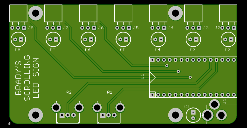
A preliminary schematic and PCB layout in EAGLE 7.7.0 had already been made. Making sure the design met all the customer requirements, I uploaded the design to OSH Park and got this nice board rendering. This I showed to Brady and he said it looked like it would work.
Schematic Diagram
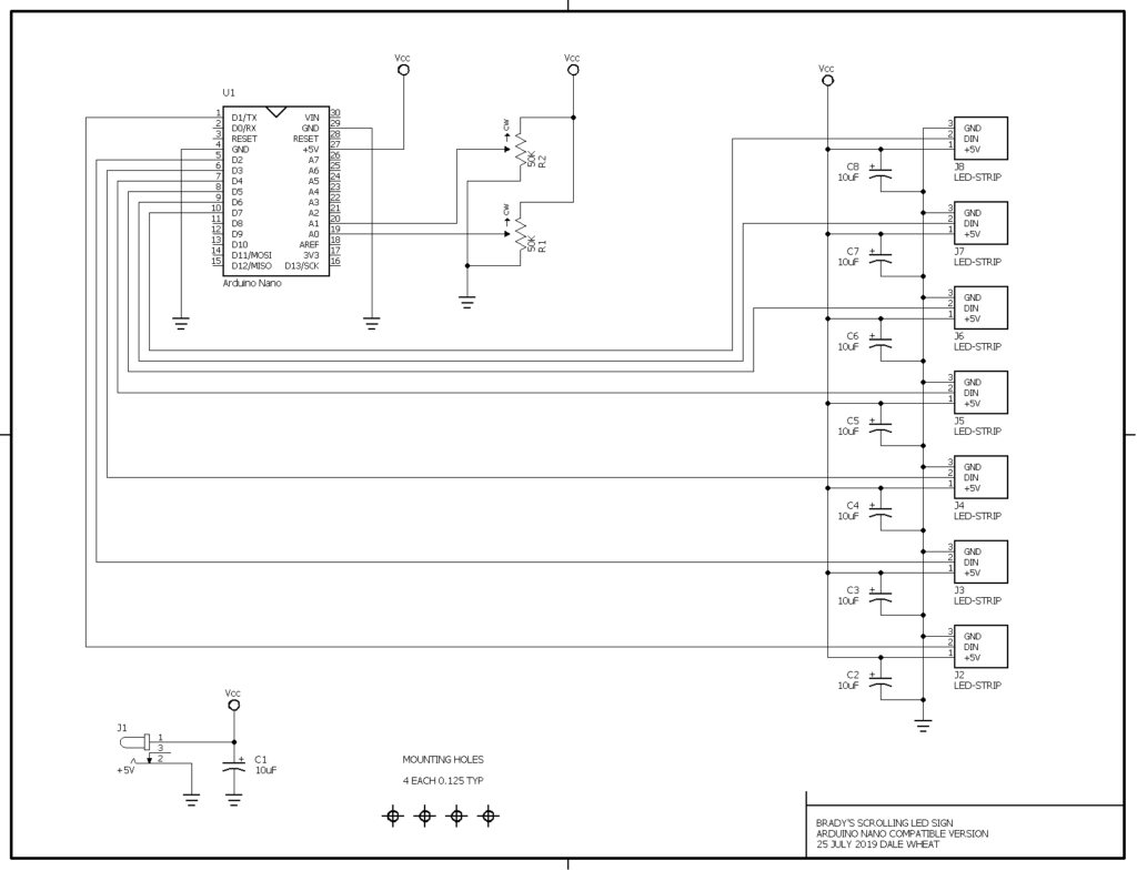
Here is the schematic diagram of the circuit. Click the image to download or view the diagram as a PDF.
Brady’s Scrolling LED Sign schematic
Customer Green Light
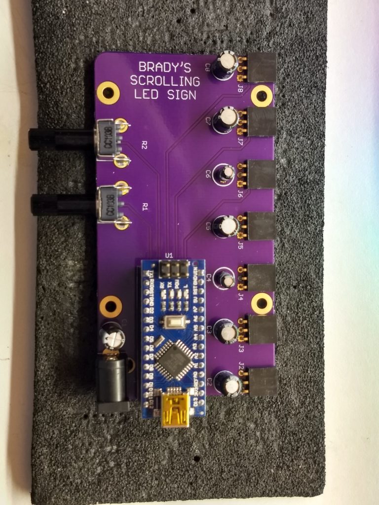
Brady’s Scrolling LED Sign PCB assembled prototype
Since everything looked good so far, on 16 October 2019 I ordered three prototype PCBs from my favorite short-run PCB fabricator, OSH Park. On 31 October 2019, the prototype boards arrived. I built one and gave it to Brady for testing. I didn’t have enough LED strips on hand to test it completely here in the lab.
On 21 November 2019, I received the remaining parts I needed to finish the second prototype PCB that I had promised Brady. The board was delivered on 26 November 2019.
A Sign of My Very Own
Animated GIF of glowy LED strip
With my one remaining prototype PCB in hand, I decided to build my own Scrolling LED Sign. I ordered a reel of NeoPixel-compatible WS2812B LEDs (5 meters, 60 LEDs per meter, 300 LEDs total) from Amazon [product link]. This was on 28 January 2020. The very next day, my order arrived. Gotta love Amazon Prime for this kind of stuff*. It even came with a “tester” device that drives the whole strip in a variety of patterns.
Since the nice, round number 300 does not divide evenly by 7, I cut up the five meter strip into six strips of 43 LEDs with one strip left over with only 42 LEDs. To plug into the sockets on the driver board, I soldered three-pin headers to the input ends of the seven strips.
*I very rarely use Amazon Prime, mostly due to concerns about sustainability, but in some situations the ultra-mega-convenience wins over my love of the Earth and its future inhabitants.
Even More Testing
Animated GIF of Brady’s Dale’s prototype Scrolling LED Sign
Laying out the loose strips on my work table, I was able to upload a slightly modified sketch and test the sign as a whole. I adjusted the number of PIXELS to 43, which was larger than Brady’s original sign.
Mounting to an Artisan Substrate
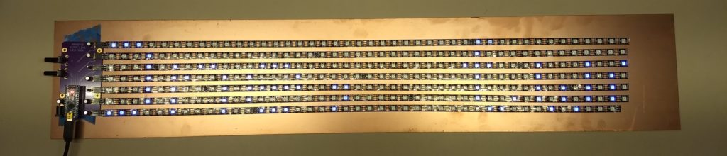
Attaching the adhesive-backed LED strips to a large panel of copper-clad PCB material I had in the lab, I was able to connect everything together. I could have scrubbed the copper to get rid of the fingerprints, etc., but I decided to leave it as it was and in fact invite oxidation, which should result in a dramatic and lovely patina in time. Since a solid sheet of copper is that very last thing you want to rest your circuits on, I put some famous blue tape under the driver board to insulate it a bit.
Dale’s Scrolling LED Sign
In Summary
Transitioning your friends to “customers” doesn’t always go well, in my experience. This experience turned out to be one of the delightful exceptions. Brady seems to be quite happy with his new signs, and I know I am. He is planning on installing one of his signs at Tanner Electronics to advertise his classes across the street at the Dallas Makerspace.
Additionally, I have created a new Scrolling LED Sign kit and added it to my web store. It’s also available at Tanner’s and BG Micro. Right now, you still need to bring your own Arduino Nano, LED strips and regulated +5VDC power supply to complete the build. I am working on sourcing all the bits to be able to offer a “complete” kit for this kind of sign. I’ll let you know when that’s available.
While waiting for my 12V Dimmer Kit PCBs to arrive, I spent a little time building yet another Cylon-style LED scanner. This time it has 12 LEDs! That’s more than 5! Quick, someone do the math!
Here’s a short video showing how it’s coming along so far. It’s still on a solderless breadboard at this stage. I’m thinking about a PCB that’s about 4 inches long and maybe one inch across, or perhaps slimmer. It should run on two AA batteries.